Ram Tough Rebuild - Cummins Engine Specs/Brief History
#1
 08-06-2008, 08:47 PM


Ram Tough Rebuild - Cummins Engine Specs
By Roy Berndt
The B-series Cummins engine may potentially go down in history as the single most important engine development project, strategic market share gain and opportunity for diversification partnerships in Cummins history.
The Cummins B-series is a family of four- and six-cylinder inline engines known as the “one-liter per cylinder” in both the popular 3.9L four-cylinder and 5.9L six-cylinder engines. The B-series is widely used in many segments, including pick-up trucks, buses, military vehicles, marine and construction equipment resulting in millions of engine sales.
The first engine (a four-cylinder B) rolled off the line July 1, 1983 and the focus by Cummins was to manufacture a “bulletproof,” trouble-free diesel, especially with the vivid memories of the troubled “V” engine series in their recent history. The 3.9L engine began its MY in 1984 as an agricultural engine for use in Case equipment. The B series was actually a joint venture between Cummins and the (troubled at the time) Case that imitated a new company called Consolidated Diesel Corp (CDC).
The B series engine family was a huge departure from Cummins’ typical large diesel core competency – and a huge gamble that paid off, resulting in more than 20 percent of Cummins’ current total production. As a result, Cummins took a huge step toward liberating itself from total dependence on the heavy-duty engine market.
Initially, Cummins needed one or more high–volume customers in the intensely competitive automotive field to realize success or the losses would be of monster proportions. After nearly a four-year pitch to Chrysler, which at the time did not have a diesel pickup like Ford and GM, the deal was done and the 5.9 B engine would go into the 1989 Ram pickups.
Chrysler did not have the engineering staff available nor with diesel experience so the responsibility fell on Cummins with nearly 20,000 engines built in 1989. Cummins actually had to prototype the first 30 vehicles for Chrysler with a new subsidiary called Cummins On-Time Assemblies (COA). It marked the first time that a medium-duty diesel engine had been used in a light duty truck. This was the only diesel that had a GVW rating of 66K limit.
Everything that anyone will ever need to know about any Cummins diesel engine can be found using the CPL (Control Parts List) on the engine data plate. The CPL identifies the performance of that engine and related parts, including the rated power at rpm and fueling rate. For the 5.9L it can be found on or near the driver side of the timing cover; combined with the engine serial number you’ll have all you need to know for a full “birth certificate” with DNA information.
In doing the research for this article I was pointed toward a book “The Engine That Could” by Jeffrey Cruikshank and David Sicilia that outlines the 75 years of Cummins history. It is a great read and I would highly recommend it for anyone in the automotive engine industry. In this article we will focus on the six-cylinder 5.9L engine that most of you would be familiar with in the Dodge Ram pickup applications. Overly simplified, there are two engines: the original design (two valves per cylinder) and the ISB (Interact System B-Series) with 4 valves per cylinder.
Cylinder Blocks
The first cylinder block design for the 6BDT 5.9L (aka the Cummins “12 valve”) was the first member of the B series family to be used in a light-duty truck. The first series engine block, although developed in 1983, was used in the Dodge Ram beginning in 1989 through 1997 and-a-half.
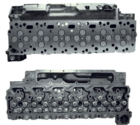
FIGURE 1
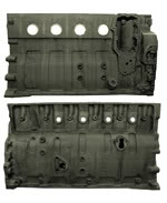
- Figure 1 First design 6BT 5.9L “12 Valve” Cummins block.
FIGURE 2
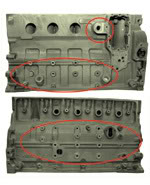
- Figure 2 Second design ISB 5.9L “24 Valve” Cummins STORM block.
The second design block, the Straight Thread O-Ring Metric (or STORM), was used beginning in 1997.5 through 2002. This block was also used in 2003 and newer off-highway applications. In 2003 the common rail fuel system awas released which used a different block (not pictured) and continued into the introduction of the new 6.7L engine in 2007.
This is the ISB 24 valve engine block application and has numerous components bolting directly to the block for maintaining compactness as well as NVH. It produced up to 235 horsepower with the Bosch VP-44 fuel system and 325 horsepower with 610 ft. lbs. of torque with the common rail fuel system. Again, there are many casting numbers but visual ID is the manner in which you will determine what it is that you have. As before, those differences are clear when looking at Figures 1 and 2.
Crankshafts
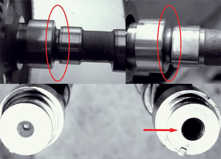
The first design crankshaft is forged steel with induction-hardened journals and eight flywheel bolts. The thrust flange is on the number 6 main journal. This crankshaft was used in the “12 valve” engine beginning in 1983 and was used from 1989 through 1997.5 and 1995.5-2002 in the Dodge Ram applications. The difference is obvious and apparent when looking at Figure 4.
FIGURE 4
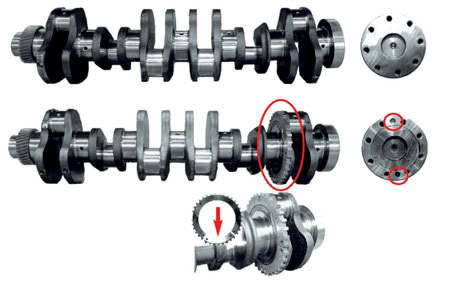
- Figure 4 The upper most crankshaft is the first design used from 1983-1997.5 and from 1999.5-2002 for Dodge applications. The crank in the middle is the second design with the crankshaft position sensor trigger ring that was used from 1997.5-2002 for non-Dodge applications. The lower inlay shows the that the trigger ring is two pieces and can easily be replaced without crank removal.
The second-generation crankshaft is forged steel and induction hardened as well. It also has 8 flywheel bolts and includes two dowel pin holes for flywheel location. This crankshaft was used from 1997.5-1999.5 for Dodge and 1997.5 through 2002 for non-Dodge application. In Figure 4 you’ll notice the slightly different relief as well as other differences. This crankshaft uses a bolt-on crankshaft position trigger ring, which is manufactured in two pieces. It could actually be replaced in-chassis if it needed to be done that way.
Connecting Rods
The earliest connecting rod used in the 5.9L Cummins has a hole in the top of the tapered pin bore and a matching bushing for lubricating the bottom piston crown. This connecting rod wrist pin area design uses a tapered pin bore connecting rod. Cummins has since replaced the wrist pin bushing with one that no longer accommodates the lubricating hole so the first design becomes fully interchangeable with the second rod.
At the crankshaft end of the connecting rod the use of a common upper- and lower-half rod bearing is worth noting since the third design does not have this design. This is a forged steel connecting rod with a “tongue and groove” type parting line, used in 1985 and 1986, but never got to the Dodge Ram. See Figure 5 and Figure 6.
FIGURE 5
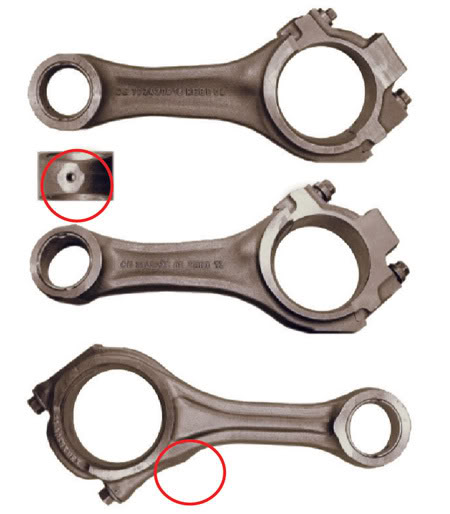
- Figure 5 The first and second connecting rod designs were identical except for oil hole in top as shown in inset. The third design rod has additional material in the forging at con rod bolt boss. All connecting rods use a tapered pin boss area.
FIGURE 6
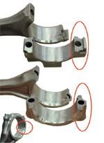
- Figure 6 The first and second series rods have “tongue-groove” design rather than the “cracked” parting line of the third design. The third design rod also has mirrored machined bearing tangs and uses two different bearing halves between upper and lower (see inset).
The second design connecting rod is the same as the first except it has no oil hole in the top of the pin bore. It does have a different casting number, but as with most Cummins components it is not necessarily the identifier you would search for. It is the oil hole in the wrist pin bore that tells all. The non-drilled rod is the only one used in Dodge ISB applications (see Figure 5 and Figure 6).
The third connecting rod design is also forged steel but the parting line is a “cracked” design. This rod however does not use the same upper and lower rod bearing because the bearing locator tabs are on the same side of the rod since both the upper and lower halves are machined in a single operation. This rod also has additional material on the beam of the forging in the area for the rod bolt boss. This rod was used beginning in 2002.5.
Last edited by RSWORDS; 08-06-2008 at 08:57 PM.
The following users liked this post:
cooterdude (09-21-2014)
#2
08-06-2008, 08:48 PM
Camshafts
The first camshaft design used a press-fit cam gear and was as-cast in the area behind the first main journal and the first cam lobe (see Figure 7). As the power output and engine RPM increased, this area proved to be the weak link of the cam and some breakage did occur. In 1991 a bolt was added to the center of the cam to strengthen the nose. It also had a fuel pump lobe in the middle of the camshaft. The basic cam design was used from 1983-1994.
FIGURE 7
The second design camshaft incorporated a shot peened and rolled radius in the area between the the front main journal and the first cam lobe to strengthen the cam (Figure 7). When the ISB was developed, it used an electric fuel pump and the fuel pump lobe was removed. The ISB cam was used from 1997.5-2002.
Cylinder Heads
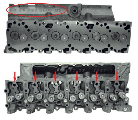
There are two different cylinder heads found on different engines. The 1st design is the �12 Valve� and will have many casting numbers more than what you really what to get into. But identification is really easy because Cummins was kind enough to cast the swirl ratio specification in 2˝ numbers right on the intake box side of the head. The quickest way to identify the early head, whether on the engine or in the vehicle, is the 6 individual rocker covers (see Figure 8).
FIGURE 8
The first design cylinder head used two different valve steam seals. First, it had a standard positive type seal in which the valve guide and spring pocket area of the cylinder head had sharp 90-degree angle machined areas that proved to be stress risers and a potential cracking area. The latter style used a top hat type seal that actually has a machined radius at the guide-to-spring pocket area eliminating the stress risers (Figure 9). This cylinder head was used from 1983 through 1997.5.
FIGURE 9
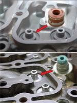
The second-generation head � the �24-valve� ISB � has a single rocker cover with the thermostat housing mount cast into the head (see Figure 10). This cylinder head was used from 1997.5 through 2002. It uses the Bosch VP-44 fuel system. The fuel line adapter is installed directly into the cylinder head and is retained by the fuel lines.
FIGURE 10
It has a tapered seat on the end to seal into the fuel injector without any type of gasket. Any attempt to remove the injector without removing the fuel line adaptor first will result in permanent damage to the injector and render it useless (Figure 11). This design is also somewhat unique in that it is a single camshaft overhead valve and uses �crossover bridges� that activate two valves simultaneously; a design feature patterned after the NH series Cummins heavy-duty diesel engine.
FIGURE 11
Pistons and Rings
The images in Figure 12 explains it all. The pistons on the left of the picture have an offset piston bowl and are for 12- valve engines. The injectors enter the combustion chamber at an angle; the design of the bowl is optimized for the angle of the injector and allows for the most efficient combustion cycle possible.
FIGURE 12
Pistons with a more pronounced curve on the outboard side of the piston bowl are for the re-entry bowl design (to cause the combustion gases to swirl in the cylinder) and are used to achieve the newer (1994 model year) emissions standards.
Also, Cummins released graded pistons (pistons with different compression heights) to more accurately achieve the correct piston protrusion to meet 1994 emission standards. (Essentially they compensate for manufacturing tolerances.)
The pistons on the right have a centered combustion bowl and are for a 24 valve engine. The injector is centered above the piston; fuel enters the combustion bowl at an optimized location. These pistons are also graded for the same reason as listed above.
The top ring location can be closer to the top of the piston or further away from the top of the piston depending on the compression ratio required (based on CPL) and is always in a ni-resist insert.
The second ring can either be installed in the aluminum piston body or in a ni-resist insert. Higher horsepower engines, or engines designed for Industrial applications will have a dual ni-resist piston design.
Dual ni-resist pistons will use dual keystone ring sets (both top rings will have notches) that aid in preventing combustion gases from leaking by the rings and into the crankcase causing oil carry-over or blow-by.
The top of the piston can either be aluminum or anodized. Anodized pistons are more robust and much less prone to cracking. This is also determined by CPL. The bottom line is that CPL and serial number will determine what piston ring combination is going to be used.
Covers and Coolers
The B series engine could experience high oil pressure spikes on cold start up (up to 130 PSI), especially in low ambient temperatures. The original design would take oil bypassed by the oil pressure regulator and route it to the oil pump inlet (dump to pump). To correct this, use an oil cooler, oil cooler cover and oil cooler gasket that takes the oil bypassed by the regulator and routes it into the oil pan (dump to sump).
(See Figure 13).
FIGURE 13
Cooler #2 is used as follows: Coolers with three-passage drillings designed for dump-to-sump lubricating systems can be used in a STORM or pre-STORM block if the engine uses a dump-to-sump oil system.
Cooler #3 is used as follows: Coolers with 3-passage drillings designed for dump-to-pump lubricating systems can only be used on STORM or pre-STORM blocks with a dump-to-pump oil system.
Gasket #1 is for a STORM Block and can be easily identified by the �window� and slot in it.
Gasket #2 is for a Pre-STORM Block. The cylinder block, oil cooler, oil cooler gasket and oil cooler cover must be matched up correctly. If not done correctly, high oil pressure or low oil pressure will be experienced.
About the Author
Roy Berndt (roy@enginebuildermag.com) has been in the automotive engine rebuilding and remanufacturing industry for over 30 years. He is an ASE Master Machinist and co-author of SAE documents and Standards. He is the EDS Data Acquistion Contractor for the Production Engine Remanufacturers Association (PERA), monthly columnist of EngINtel for Engine Builder magazine and Program Manager for PROFormance Powertrain Products, a PER in Springfield, MO.
--------------------------------------------------------------------------------
LINK TO ARTICLE
Ram Tough Rebuild: Engine Builder
The first camshaft design used a press-fit cam gear and was as-cast in the area behind the first main journal and the first cam lobe (see Figure 7). As the power output and engine RPM increased, this area proved to be the weak link of the cam and some breakage did occur. In 1991 a bolt was added to the center of the cam to strengthen the nose. It also had a fuel pump lobe in the middle of the camshaft. The basic cam design was used from 1983-1994.
FIGURE 7
- Figure 7 The first design camshaft (top left) is as cast between the first main and first lobe where the second design had a rolled radius (top right). The bottom picture explains the hole for the additional bolt for strengthening the cam bore.
The second design camshaft incorporated a shot peened and rolled radius in the area between the the front main journal and the first cam lobe to strengthen the cam (Figure 7). When the ISB was developed, it used an electric fuel pump and the fuel pump lobe was removed. The ISB cam was used from 1997.5-2002.
Cylinder Heads
There are two different cylinder heads found on different engines. The 1st design is the �12 Valve� and will have many casting numbers more than what you really what to get into. But identification is really easy because Cummins was kind enough to cast the swirl ratio specification in 2˝ numbers right on the intake box side of the head. The quickest way to identify the early head, whether on the engine or in the vehicle, is the 6 individual rocker covers (see Figure 8).
FIGURE 8
- Figure 8 First design �12-Valve� cylinder head with intake swirl specifications cast into head (top) and six individual rocker covers (bottom).
The first design cylinder head used two different valve steam seals. First, it had a standard positive type seal in which the valve guide and spring pocket area of the cylinder head had sharp 90-degree angle machined areas that proved to be stress risers and a potential cracking area. The latter style used a top hat type seal that actually has a machined radius at the guide-to-spring pocket area eliminating the stress risers (Figure 9). This cylinder head was used from 1983 through 1997.5.
FIGURE 9
- Figure 9 The upper image shows the early design seal with sharp machining edges in spring pocket area. The lower images shows top hat type seal with radius spring pocket area.
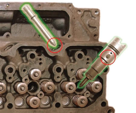
The second-generation head � the �24-valve� ISB � has a single rocker cover with the thermostat housing mount cast into the head (see Figure 10). This cylinder head was used from 1997.5 through 2002. It uses the Bosch VP-44 fuel system. The fuel line adapter is installed directly into the cylinder head and is retained by the fuel lines.
FIGURE 10
- Figure 10 The second series �24 Valve� ISB engine uses �cross over� bridges to activate two valves with one rocker.
It has a tapered seat on the end to seal into the fuel injector without any type of gasket. Any attempt to remove the injector without removing the fuel line adaptor first will result in permanent damage to the injector and render it useless (Figure 11). This design is also somewhat unique in that it is a single camshaft overhead valve and uses �crossover bridges� that activate two valves simultaneously; a design feature patterned after the NH series Cummins heavy-duty diesel engine.
FIGURE 11
- Figure 11 Attempting to remove an injector from an ISB head without first removing the fuel line adapter will permanently damage the injectors.
Pistons and Rings
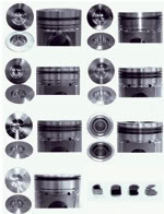
The images in Figure 12 explains it all. The pistons on the left of the picture have an offset piston bowl and are for 12- valve engines. The injectors enter the combustion chamber at an angle; the design of the bowl is optimized for the angle of the injector and allows for the most efficient combustion cycle possible.
FIGURE 12
- Figure 12 On the left, pistons for the 12-valve engines; on the right, pistons for the 24-valve engines. See the article for descriptions.
Pistons with a more pronounced curve on the outboard side of the piston bowl are for the re-entry bowl design (to cause the combustion gases to swirl in the cylinder) and are used to achieve the newer (1994 model year) emissions standards.
Also, Cummins released graded pistons (pistons with different compression heights) to more accurately achieve the correct piston protrusion to meet 1994 emission standards. (Essentially they compensate for manufacturing tolerances.)
The pistons on the right have a centered combustion bowl and are for a 24 valve engine. The injector is centered above the piston; fuel enters the combustion bowl at an optimized location. These pistons are also graded for the same reason as listed above.
The top ring location can be closer to the top of the piston or further away from the top of the piston depending on the compression ratio required (based on CPL) and is always in a ni-resist insert.
The second ring can either be installed in the aluminum piston body or in a ni-resist insert. Higher horsepower engines, or engines designed for Industrial applications will have a dual ni-resist piston design.
Dual ni-resist pistons will use dual keystone ring sets (both top rings will have notches) that aid in preventing combustion gases from leaking by the rings and into the crankcase causing oil carry-over or blow-by.
The top of the piston can either be aluminum or anodized. Anodized pistons are more robust and much less prone to cracking. This is also determined by CPL. The bottom line is that CPL and serial number will determine what piston ring combination is going to be used.
Covers and Coolers
The B series engine could experience high oil pressure spikes on cold start up (up to 130 PSI), especially in low ambient temperatures. The original design would take oil bypassed by the oil pressure regulator and route it to the oil pump inlet (dump to pump). To correct this, use an oil cooler, oil cooler cover and oil cooler gasket that takes the oil bypassed by the regulator and routes it into the oil pan (dump to sump).
(See Figure 13).
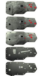
FIGURE 13
- Figure 13 Oil coolers and gaskets can give you fits if used in the wrong combination, with either extremely high or low oil pressure, when used in the incorrect combinations.
Cooler #2 is used as follows: Coolers with three-passage drillings designed for dump-to-sump lubricating systems can be used in a STORM or pre-STORM block if the engine uses a dump-to-sump oil system.
Cooler #3 is used as follows: Coolers with 3-passage drillings designed for dump-to-pump lubricating systems can only be used on STORM or pre-STORM blocks with a dump-to-pump oil system.
Gasket #1 is for a STORM Block and can be easily identified by the �window� and slot in it.
Gasket #2 is for a Pre-STORM Block. The cylinder block, oil cooler, oil cooler gasket and oil cooler cover must be matched up correctly. If not done correctly, high oil pressure or low oil pressure will be experienced.
About the Author
Roy Berndt (roy@enginebuildermag.com) has been in the automotive engine rebuilding and remanufacturing industry for over 30 years. He is an ASE Master Machinist and co-author of SAE documents and Standards. He is the EDS Data Acquistion Contractor for the Production Engine Remanufacturers Association (PERA), monthly columnist of EngINtel for Engine Builder magazine and Program Manager for PROFormance Powertrain Products, a PER in Springfield, MO.
--------------------------------------------------------------------------------
LINK TO ARTICLE
Ram Tough Rebuild: Engine Builder
Last edited by DIESELDENT; 09-13-2009 at 12:18 PM.
The following 5 users liked this post by RSWORDS:
00' Quad Cab (09-13-2009),
97cummins (08-09-2008),
harry22 (08-20-2010),
Horns (09-16-2010),
wildbill (10-16-2008)
#3
08-07-2008, 12:22 AM


#6
10-16-2008, 07:19 PM

Diesel Fan
Join Date: Aug 2008
Location: Nosebleed Country Colorado
Posts: 42
Received 0 Likes
on
0 Posts
Hey, nice post!
How critical is piston protrusion on a 24V? Does it just affect emissions or will it affect performance. I had my block decked and O-ring'd, and my pistons coated, I don't know what my piston protrusion is yet, (my pistons, rods, crank etc. are being balanced) I just wanted to know how critical it is. Hopefully it's within spec!
S.N. is 45745533 and the CPL is 2446


Thread
Thread Starter
Forum
Replies
Last Post
burndiesel
24 Valve 2nd Gen Dodge Cummins 98.5-02
10
02-07-2023 01:15 AM
Genos Garage
Genos Garage
0
08-03-2015 09:29 AM
Diesel Bombers
Latest Automotive Industry News
0
03-13-2015 09:20 AM
Diesel Bombers
General Diesel Related
0
10-20-2014 08:10 AM


